- Benjamin Patterson Branding Cultural Design for Change Digital Design Education Environment Motion Graphics User Experience Visual Communication Design benjamin-patterson
- Ali Pierse Future Technologies Politics Protest Research Social Justice New Media Studies ali-pierse
- Darragh Scott New Media Studies darragh-scott
- John Mc Kiernan Book Environment Film Music Radio Research Television Website New Media Studies john-mc-kiernan
- Evan Clarke Cultural Education Research Social Justice New Media Studies evan-clarke
- Connor Coleman Branding Environment Film Radio Research Television New Media Studies connor-p-coleman
- Emily Dover Cultural Education Family History Radio New Media Studies emily-a-dover
- Conor Duggan Ethics Government Politics Research Social Justice Website New Media Studies conor-duggan
- Aoife McCaffrey New Media Studies aoife-mc-caffrey
- Alannah Hanley Fashion History Research Social Justice Website New Media Studies alannah-hanley
- Orla McGuirk Life Sciences Psychology Cyberpsychology orla-mc-guirk
- Danny Snow Music Psychology Cyberpsychology daniel-snow
- Charlit Floriano 3D Character Design Digital Design Future Technologies Game Design 3D Animation charlit-floriano
- Jianxing Mao 3D Design Thinking Research 3D Animation jianxing-mao
- xi zhang 3D Animation xi-zhang
- Wynette Aplasen Cultural Diversity Equality Ethics Social Justice Television New Media Studies wynette-aplasen
- Colin Sharkey App Covid-19 Design Thinking Digital Design Future Technologies Research User Experience Website User Experience Design colin-sharkey
- Clodagh Sheridan App Psychology User Experience User Experience Design clodagh-sheridan
- Alexander Stewart Accessibility App Education User Experience User Experience Design alexander-stewart
- Denise Dunne Psychology Cyberpsychology denise-dunne
- Sarah Harcourt Thewlis Diversity Education Healthcare Psychology Research Science Cyberpsychology sarah-harcourt-thewlis
- Rachel Malone Psychology Sports + Fitness Cyberpsychology rachel-malone
- Juliana Rosa User Experience Design juliana-rosa
- Jonathon Ryan App Covid-19 Data Visualisation Design Thinking Digital Design Future Technologies Government Healthcare Life Sciences Psychology Research Science User Experience Website User Experience Design jonathon-m-ryan
- Benjamin Shanahan App Covid-19 Ethics User Experience User Experience Design benjamin-shanahan
- Victoria Anderson Data Visualisation Design for Change Digital Design Government Politics User Experience Website User Experience Design victoria-anderson
- Rory Bradley App Design Thinking Future Technologies Product Design Research User Experience User Experience Design rory-bradley
- Georgia Collard Accessibility App Design for Change Design Thinking Digital Design Diversity Education Ethics Product Design User Experience User Experience Design georgia-collard
- Lauren Day Design Thinking Research User Experience User Experience Design lauren-day
- Emily Rhona Whitty Kelly Creative Music Production emily-whitty-kelly
- Adam Rossiter Website Creative Computing adam-rossiter
- Darryl Sullivan App Business Data Visualisation Creative Computing darryl-sullivan
- Mark Sweeney App Healthcare Research User Experience Creative Computing mark-sweeney
- Niall Delahan 3D Entrepreneurship Future Technologies Healthcare Installation Music Performance Psychology Science Creative Music Production niall-m-delahan
- Evie Dredge Family Music Psychology Creative Music Production eithne-dredge
- Seán Egan Branding Covid-19 Music Creative Music Production sean-egan
- Ruairí Forde Music Creative Music Production ruairi-forde
- Roya Golchini Education Music Psychology Research Creative Music Production roya-golchini
- Craig Gray Cultural Future Technologies History Music Psychology Research Science User Experience Creative Music Production craig-gray
- Áine Hartnett Music Psychology Creative Music Production aine-hartnett
- Cathal T Hughes Finance Music Research Creative Music Production cathal-t-hughes
- Ryan Jeffares App Education Game Design Music Product Design Research User Experience Creative Music Production ryan-d-jeffares
- Rhys Mayes Film Future Technologies Music Creative Music Production rhys-d-mayes
- Kieran Murphy Digital Design Engineering Music Product Design Research Creative Music Production kieran-murphy
- Faye Donohoe Covid-19 Cultural Data Visualisation Education Healthcare Research Creative Computing faye-donohoe
- Michael Egan App Transport + Travel User Experience Website Creative Computing michael-egan
- Darren Fagan App Data Visualisation Research Website Creative Computing darren-fagan
- Matt Hill App Business Data Visualisation Entrepreneurship Management User Experience Website Creative Computing matthew-hill
- Shane Kelly Accessibility App Finance Management User Experience Creative Computing shane-kelly
- Ross MacDonald Website Creative Computing ross-macdonald
- Vivienne Mulvey AI App Business Finance Management Creative Computing vivienne-mulvey
- Eoan O’Dea App Business Cybersecurity Design Thinking Digital Design Education Engineering Entrepreneurship Future Technologies Game Design Music Creative Computing eoan-odea
- Hannah O’Donoghue App Creative Computing hannah-odonoghue
- John Carlo M. Ramos Accessibility App Design Thinking Digital Design Education Healthcare Product Design Research User Experience Creative Computing john-c-ramos
- Jurizza Cuaresma Website Creative Computing jurizza-r-cuaresma
- Aileen Denton 3D Accessibility Diversity Game Design Research User Experience Creative Computing aileen-denton
- Sam Cox Engineering Music Product Design Creative Media Technologies samual-k-cox
- Peter Egan AI Engineering Future Technologies Radio Research Science Space Exploration User Experience Creative Media Technologies peter-egan
- Cian Hannon Covid-19 Design Thinking Energy Engineering Environment Future Technologies Product Design Research Science Website Creative Media Technologies cian-hannon
- Adam Harvey Accessibility Education Music Performance Creative Media Technologies adam-harvey
- Josh Henvey Engineering Music Product Design Creative Media Technologies josh-henvey
- Adam Herdman Creative Media Technologies adam-herdman
- Hugh Kennedy Crime Data Visualisation Engineering Research Science Creative Media Technologies hugh-kennedy
- Christopher McQuillan Engineering Music Product Design Creative Media Technologies christopher-mcquillan
- Ryan Sheridan Creative Media Technologies ryan-sheridan
- Colin Synnott Data Visualisation Creative Media Technologies colin-synnott
- Andrew Bell Creative Computing andrew-bell
- Maeriel J Benedicto Website Creative Computing maeriel-j-benedicto
- James Blair Data Visualisation Digital Design Game Design Transport + Travel Creative Computing james-blair
- Dylan Chan 3D AI Architecture Environment Game Design User Experience Wildlife Creative Computing dylan-chan
- Eoin Clancy App Performance Creative Computing eoin-l-clancy
- Matthew Collins App Data Visualisation Website Creative Computing matthew-collins
- Cat Leibowitz Film Film + Television Production caitlin-leibowitz
- Martha Lovett Cullen Film Film + Television Production martha-lovett-cullen
- Louis Maxwell Film Film + Television Production louis-maxwell
- Olivia O’Malley Film + Television Production olivia-omalley
- Ruairí O’Neill Film Television Film + Television Production ruairi-oneill
- Bláthnaid O’Toole Film + Television Production blathnaid-otoole
- Alan Power Film Radio Film + Television Production alan-power
- Dario Saliani Film Film + Television Production dario-saliani
- Kevin Scott Film Film + Television Production kevin-r-scott
- Dan Seymour Film Television Film + Television Production daniel-seymour
- Stephen Sorensen Film Film + Television Production stephen-sorensen
- Ben Spillane Film Film + Television Production ben-t-spillane
- Simone Tringali Film Television Film + Television Production simone-tringali
- Annie Walsh Covid-19 Film Motion Graphics Politics Television Film + Television Production annie-walsh
- Fia Karma Wren Film + Television Production fia-wren
- Bryan Agar Business Data Visualisation Digital Design History Property User Experience Website Creative Media Technologies bryan-agar-cox
- Conor Brereton Creative Media Technologies conor-brereton
- Anton Candelaria Data Visualisation Creative Media Technologies anton-y-candelaria
- Amber O’Shea 3D Advertising Branding Covid-19 Design Thinking Digital Design Exhibition Design Fashion Future Technologies Installation Print Making Psychology Sculpture User Experience Website Photography amber-oshea
- Chlöe Scanlan Photography chloe-scanlan
- Aoife Louise Photography aoife-louise
- Robert Bass Film Film + Television Production robert-bass
- Zoë Boss Film Motion Graphics Film + Television Production zoe-j-boss
- Aidan Buckley Film Television Film + Television Production aidan-buckley
- Eoin Byrne Design Thinking Drawing Film Lighting Design Music Painting Performance Product Design Television Film + Television Production eoin-a-byrne
- Killian Casey Film + Television Production killian-casey
- Ruairí Coughlan Film Television Film + Television Production ruairi-coughlan
- Alec Delaney Film + Television Production alec-delaney
- Jamie Dixon Film Lighting Design Film + Television Production jamie-dixon
- Jack Fahy Film Television Film + Television Production jack-fahy
- Sam Fallover Film + Television Production sam-fallover
- Tara Farrell Film + Television Production tara-m-farrell
- Ethan Forbes-Roe Energy Film Music Film + Television Production ethan-forbes-roe
- Conor Forkin Advertising Film Government History Motion Graphics Television Film + Television Production conor-forkin
- Cara Gaynor Film Film + Television Production cara-gaynor
- Jacob Goode Film Film + Television Production jacob-goode
- Ethan Jones Film Film + Television Production ethan-jones
- Stephen Kyne Television Film + Television Production stephen-kyne
- Lisa McDonald Design Thinking Digital Design Exhibition Design Film Installation Lighting Design Music Animation lisa-mcdonald
- Kayde Middleton Design Thinking Drawing Film Illustration Set Design Animation kayde-middleton
- Patrick O’Callaghan Environment Family Fashion Film History Illustration Installation Painting Social Justice Wildlife Animation patrick-ocallaghan
- Olga Pelihh Film Illustration Lighting Design Motion Graphics Painting Animation olga-pelihh
- Sean Roberts 3D Drawing Film Illustration Motion Graphics Animation sean-roberts
- Marta Sniezek Character Design Digital Design Drawing Film Illustration Motion Graphics Painting Animation marta-sniezek
- Christian Spurling Drawing Film Illustration Painting Animation christian-spurling
- Abigail Webster Character Design Digital Design Film Illustration Animation abigail-p-webster
- Eimear Young Character Design Drawing Film Illustration Animation eimear-young
- Mark Dupré Cultural Exhibition Design Fashion Painting Sculpture Set Design Photography mark-cavanagh
- Sarah-Jane Kehoe Film Print Making Website Photography sarah-j-kehoe
- Tyler Kelly Photography tyler-kelly
- Indigo I Lewisohn Equality Fashion Photography indigo-i-lewisohn
- Sarah Louise Lordan Performance Psychology Photography sarah-l-lordan
- Simon Meagher Photography simon-c-meagher
- Leon Nevill Gallagher Cultural Data Visualisation Exhibition Design Future Technologies Installation Print Making Sculpture Photography leon-nevill-gallagher
- Patrick O’Byrne Cultural Film Installation Photography patrick-obyrne
- Rebekah Bustos Character Design Design Thinking Digital Design Film Illustration Product Design Set Design Television Production Design rebekah-bustos
- Maisie Grace Hourihane 3D Architecture Cultural Digital Design Drawing Environment Film Illustration Installation Lighting Design Performance Set Design Production Design maisie-hourihane
- Aoife Kelly 3D Digital Design Drawing Set Design Production Design aoife-c-kelly
- Eva Bernadette Kelly Character Design Design Thinking Digital Design Drawing Film Illustration Lighting Design Set Design Production Design eva-b-kelly
- Niamh Lynam Architecture Drawing Film Set Design Production Design niamh-lynam
- Aoife McIntyre 3D Film Lighting Design Performance Set Design Television Production Design aoife-mcintyre
- Sally Nolan Architecture Digital Design Film Lighting Design Set Design Production Design sally-nolan
- Ciara Croke 3D Character Design Drawing Film Animation ciara-croke
- Aoibh Foynes Character Design Digital Design Drawing Film Illustration Animation aoibh-foynes
- Deither Kirby Jay Character Design Drawing Film Illustration Music Painting Television Animation deither-k-jay
- Jessie Lopez II 3D Drawing Film Illustration Music Painting Animation jessie-i-lopez
- Julia Malinowska 3D Character Design Drawing Film Game Design Illustration Painting Animation julia-malinowska
- Ellen McCullough Family Film Animation ellen-mccullough
- Jane Mimnagh Character Design Drawing Fashion Film Costume Design jane-mimnagh
- Conor Morrin Character Design Design Thinking Digital Design Drawing Fashion Film Illustration Research Costume Design conor-morrin
- Roisín Ní Ghabhann Character Design Fashion Costume Design roisin-ni-gabhann
- Aoife O’Callaghan Character Design Costume Design aoife-ocallaghan
- Hazel Ryan 3D Character Design Design Thinking Digital Design Drawing Environment Fashion Film History Illustration Performance Set Design Space Exploration Costume Design hazel-ryan
- Leanne Scanlon Costume Design leanne-scanlon
- Judith Smolenski 3D Character Design Drawing Fashion Future Technologies Illustration Costume Design judith-smolenski
- Saoirse Carey 3D Character Design Digital Design Drawing Film Illustration Painting Website Character MakeUp Design saoirse-carey
- Angelika Krasinska Cultural Family Film Television Character MakeUp Design angelika-m-krasinska
- Jenni Monahan Character Design Character MakeUp Design jennifer-monahan
- Anna M. O’Brien Character MakeUp Design anna-m-obrien
- Caitlin O’Donnell 3D Character Design Design Thinking Film Sculpture Character MakeUp Design caitlin-odonnell
- Klaudia Rapala 3D Character Design Cultural Drawing Film Illustration Set Design Character MakeUp Design klaudia-rapala
- Kim Ryan Character Design Digital Design Fashion Film Performance Sculpture Set Design Character MakeUp Design kim-ryan
- Isobel Shackleton Character Design Drawing Illustration Character MakeUp Design isobel-shackleton
- Saoirse Whelan Character Design Painting Sculpture Character MakeUp Design saoirse-whelan
- Louise Holohan 3D Sculpture Set Design 3D Design Modelmaking + Digital Art louise-holohan
- Alice Horan 3D Character Design Crime Cultural Film History Psychology 3D Design Modelmaking + Digital Art alice-horan
- Arkadiusz Kania 3D Architecture Character Design Digital Design Game Design 3D Design Modelmaking + Digital Art arkadiusz-kania
- Sarah Leech 3D Character Design Sculpture 3D Design Modelmaking + Digital Art sarah-leech
- Yaroslava Leivshina 3D Character Design Covid-19 Cultural Film 3D Design Modelmaking + Digital Art yaroslava-leivshina
- Dylan Leonard 3D Character Design Design for Change Film Performance Sculpture Wildlife 3D Design Modelmaking + Digital Art dylan-leonard
- El McCarthy 3D Digital Design Game Design 3D Design Modelmaking + Digital Art ellen-mccarthy
- Kyle McElhinney 3D Character Design Digital Design Film Space Exploration Television 3D Design Modelmaking + Digital Art kyle-j-mcelhinney
- Emma McEneaney 3D Character Design 3D Design Modelmaking + Digital Art emma-mceneaney
- Tara McNally Architecture Digital Design Drawing Film Product Design Set Design 3D Design Modelmaking + Digital Art tara-mcnally
- Regina Muldoon 3D Character Design Digital Design Drawing Film Sculpture Television 3D Design Modelmaking + Digital Art regina-m-muldoon
- Gabriele Noruisyte 3D Character Design Covid-19 Film Sculpture 3D Design Modelmaking + Digital Art gabriele-noruisyte
- Shane D. O’Broin 3D Character Design Sculpture 3D Design Modelmaking + Digital Art shane-d-obroin
- Momo Willet 3D Design for Change Research Sculpture Set Design 3D Design Modelmaking + Digital Art maura-willet-osullivan
- Mar Blay Gomez Character Design Design Thinking Digital Design Drawing Film Illustration Television Costume Design maria-del-mar-blay-gomez
- Matthew Shiell Character Design Drawing Energy Film Illustration Space Exploration Art matthew-d-shiell
- Rebecca Warren 3D Sculpture Art rebecca-warren
- Katie Whelan Drawing Painting Art katie-whelan
- Stevie Wilson Cultural Film Art stevie-wilson
- Elena Larionova Film Film + Television Production elena-larionova
- Izabela Wojewoda Drawing Exhibition Design Illustration Installation Wildlife Art izabela-wojewoda
- Laura Boggans 3D Architecture Cultural Design Thinking Drawing History Lighting Design Painting Research Sculpture Set Design Space Exploration 3D Design Modelmaking + Digital Art laura-boggans
- Emmett Brennan 3D Character Design Game Design 3D Design Modelmaking + Digital Art emmett-brennan
- Dylan Carroll Character Design Engineering Film Future Technologies Performance Sculpture Space Exploration Television 3D Design Modelmaking + Digital Art dylan-carroll
- Deryn Casey 3D Character Design 3D Design Modelmaking + Digital Art deryn-casey
- Rachel Cogley Architecture Cultural Education Environment Ethics History Painting Research Sculpture Set Design Transport + Travel User Experience Wildlife 3D Design Modelmaking + Digital Art rachel-cogley
- Kevin De Búrca 3D Character Design Digital Design Game Design 3D Design Modelmaking + Digital Art kevin-de-burca
- Timothy Dignam 3D Film Space Exploration 3D Design Modelmaking + Digital Art timothy-dignam
- Nicole Dolan 3D Film Set Design 3D Design Modelmaking + Digital Art nicole-dolan
- Simona Donzelli 3D Accessibility Architecture Design for Change Digital Design Diversity Education Equality Ethics Future Technologies Game Design Performance User Experience 3D Design Modelmaking + Digital Art simona-donzelli
- Alison Dooley 3D Digital Design Film Installation Painting Sculpture Television 3D Design Modelmaking + Digital Art alison-dooley
- Roberta Doorley 3D Book Design for Change Environment Healthcare Sculpture Social Justice 3D Design Modelmaking + Digital Art roberta-j-doorley
- Joanne Finnegan 3D Character Design Film Painting Sculpture 3D Design Modelmaking + Digital Art joanne-finnegan
- Gavin Flanagan 3D Design Modelmaking + Digital Art gavin-flanagan
- Fiona Gorman 3D Design Modelmaking + Digital Art fiona-gorman
- Ciaran Gormley 3D Game Design 3D Design Modelmaking + Digital Art ciaran-gormley
- Maureen Fitzpatrick Art mary-e-fitzpatrick
- Patrick Fitzsimons Energy Environment Film Motion Graphics Performance Art patrick-fitzsimons
- Grace Hanley Drawing Environment Exhibition Design Illustration Painting Science Wildlife Art grace-hanley
- Sarah Hanly Painting Art sarah-hanly
- Steffi Kelly Installation Print Making Research Sculpture Art stephanie-kelly
- Patryk Kurkowski Digital Design Music Art patryk-kurkowski
- Danny Lalor Fitzpatrick Film Art danny-lalor-fitzpatrick
- Jessica Leonard Drawing Installation Sculpture Art jessica-leonard
- Sophie Luck 3D Advertising Covid-19 Cultural Design for Change Ethics Film Installation Performance Sculpture Set Design Art sophie-luck
- Henry Malone 3D Environment Art henry-malone
- Mollie McCullough Drawing Art mollie-mccullough
- Saoirse Melia Art saoirse-melia
- Aoife Murphy Architecture Crime Drawing Environment Ethics History Illustration Art aoife-murphy
- Aoibheann Ní Ealaí 3D Cultural Installation Painting Psychology Research Sculpture Art aoibheann-ni-ealai
- Ell O’Farrell Film Art emily-a-ofarrell
- Diana Popa Film Art diana-popa
- Aoife Ruth Drawing Environment Painting Print Making Art aoife-ruth
- Lauren Conway Cultural Data Visualisation Design for Change Design Thinking Diversity Drawing Education Exhibition Design Government History Illustration Installation Painting Politics Protest Research Social Justice Art lauren-m-shaw-conway
- Seán Tait Branding Design for Change Digital Design Environment Ethics Illustration Motion Graphics Protest Social Justice Website Visual Communication Design sean-tait
- Craig Thiel 3D App Branding Digital Design Exhibition Design Illustration Motion Graphics Product Design User Experience Website Visual Communication Design paul-c-thiel
- Suran Tierney App Branding Design for Change Design Thinking Digital Design Equality Motion Graphics Website Visual Communication Design chloe-s-tierney
- Linda Tucker Advertising App Branding Digital Design Exhibition Design Wildlife Visual Communication Design linda-tucker
- Thomas Wakely Branding Engineering Environment Future Technologies Illustration Motion Graphics Space Exploration Website Visual Communication Design thomas-wakely
- Jess Whelan App Branding Cybersecurity Digital Design Exhibition Design Motion Graphics User Experience Website Visual Communication Design jessica-whelan
- Olwen Wymer Branding Design for Change Design Thinking Digital Design Drawing Exhibition Design Illustration Motion Graphics Visual Communication Design olwen-wymer
- Karolina Adamczak Film Performance Art karolina-adamczak
- Ciara Campbell 3D Environment Installation Research Sculpture Wildlife Art ciara-campbell
- Rebecca Campbell Film Art rebecca-campbell
- Lee Campbell Perrie 3D Digital Design Environment Exhibition Design Film Future Technologies Game Design Installation Sculpture Art lee-campbell-perrie
- Nicola Chambers 3D Lighting Design Sculpture Art nicola-chambers
- Ellen Connor 3D Drawing Installation Art ellen-connor
- Milo Cummins Film Music Performance Art milo-cummins
- Kaylem Davis Drawing Art kaylem-davis
- Claire Donohoe Drawing Environment Illustration Installation Print Making Wildlife Art claire-donohoe
- Will Doyle 3D Architecture Drawing Installation Painting Sculpture Art william-doyle
- Séamus Duffy Art seamus-duffy
- Rhiannon Elliott Art rhiannon-elliott
- Jane Ellis Drawing Painting Print Making Art jane-ellis
- Emerald Gibson App Branding Design for Change Diversity Fashion Motion Graphics User Experience Visual Communication Design emerald-gibson
- Lara Glynn App Branding Charity Design for Change Design Thinking Digital Design Education Equality Ethics Illustration Motion Graphics Psychology Website Visual Communication Design lara-glynn
- Muirín Goulding Advertising App Branding Character Design Cultural Design for Change Design Thinking Digital Design Diversity Drawing Education Environment Equality Exhibition Design Family History Illustration Motion Graphics Music Politics Print Making Product Design Research Social Justice User Experience Website Visual Communication Design muirin-g-goulding
- Éadaoin Hennessy AI App Branding Design for Change Design Thinking Digital Design Family Healthcare Product Design Research User Experience Visual Communication Design eadaoin-hennessy
- Carla Henry App Branding Business Charity Covid-19 Design for Change User Experience Website Visual Communication Design carla-henry
- Róisín Jordan Branding Design for Change Digital Design Education User Experience Website Visual Communication Design roisin-jordan
- Lauren Kilroy Advertising Branding Design for Change Design Thinking Digital Design Diversity Energy Exhibition Design Motion Graphics Sports + Fitness User Experience Website Visual Communication Design lauren-kilroy
- Morna McCullagh Cultural Design for Change Protest Visual Communication Design morna-mccullagh
- Samuel McSherry App Branding Design for Change Education Product Design User Experience Website Visual Communication Design samuel-mcsherry
- Stacey O’Carroll Advertising App Design Thinking Digital Design Environment User Experience Visual Communication Design stacey-ocarroll
- Cillian Ó Gaora Advertising AI App Branding Business Design for Change Design Thinking Digital Design Drawing Education Entrepreneurship Environment Illustration Motion Graphics User Experience Visual Communication Design cillian-o-gaora
- Iseult O’Maonaigh Design Thinking Digital Design Illustration Motion Graphics User Experience Website Visual Communication Design iseult-a-o-maonaigh
- Aisling O’Reilly App Branding Design for Change Design Thinking Digital Design Education Environment Illustration Product Design Psychology Research User Experience Website Wildlife Visual Communication Design aisling-oreilly
- Lucy Power Branding Design for Change Design Thinking Digital Design Equality Family Healthcare Illustration Product Design User Experience Visual Communication Design lucy-j-power
- Kate Sheehan Branding Design Thinking Digital Design Exhibition Design Healthcare Illustration Product Design Research User Experience Website Visual Communication Design kate-sheehan
- Claire Smith Branding Digital Design User Experience Website Visual Communication Design claire-smith
- Luke Steele Visual Communication Design luke-steele
- Adam Szalowski 3D Future Technologies Healthcare Motion Graphics Psychology Website Visual Communication Design adam-szalowski
- Tash Milne Psychology User Experience Applied Psychology natasha-milne
- Orla Mullett Business Covid-19 Healthcare Life Sciences Psychology Research Science Applied Psychology orla-mullett
- Kate Naughton Covid-19 Design for Change Environment Healthcare Psychology Research Applied Psychology kate-naughton
- Muireann O’Connor Education Psychology Research Science Sports + Fitness Applied Psychology muireann-a-oconnor
- Aidan O’Keeffe Accessibility Design Thinking Psychology User Experience Applied Psychology aidan-t-okeeffe
- Lillian Searson Future Technologies Psychology Applied Psychology lillian-i-searson
- Emma Tobin Healthcare Psychology Research Science Sports + Fitness Applied Psychology emma-tobin
- Luke Tynan Psychology Applied Psychology luke-tynan
- Jasmine Woods Psychology Research Applied Psychology jasmine-woods
- Rowan Black Digital Design Visual Communication Design rowan-d-black
- Evie Brook App Branding Digital Design Education Exhibition Design User Experience Visual Communication Design eve-brook
- Zhi Yang Lu Covid-19 Psychology Research Science Applied Psychology zhi-y-lu
- Jack MacHugh Psychology Research Applied Psychology jack-t-mac-hugh
- Laura Mahady Psychology Applied Psychology laura-mahady
- Francis McDonnell Accessibility Covid-19 Cybersecurity Design Thinking Life Sciences Psychology Research Social Justice User Experience Applied Psychology francis-mcdonnell
- Denis McKeown Education Life Sciences Psychology Research Science Sports + Fitness Applied Psychology denis-mckeown
- Heather McLean Psychology Applied Psychology heather-mclean
- Jennifer Meagher Business Covid-19 Psychology Applied Psychology jennifer-meagher
- Louise Horan Gahan Healthcare Psychology Research Science Applied Psychology louise-m-horan-gahan
- Edward Bickers Education Performance Psychology Applied Psychology edward-bickers
- Ellen Boucher Covid-19 Psychology Research Applied Psychology ellen-boucher
- Camilla Chioato Business Design for Change Education Performance Psychology Research Applied Psychology camilla-chioato
- Sinéad Doyle Psychology Sports + Fitness Applied Psychology sinead-doyle
- Michael Fortune Covid-19 Psychology User Experience Applied Psychology michael-fortune
- 3D Animation
- 3D Design Modelmaking + Digital Art
- Animation
- Applied Psychology
- Art
- Character MakeUp Design
- Costume Design
- Creative Computing
- Creative Media Technologies
- Creative Music Production
- Cyberpsychology
- Film + Television Production
- New Media Studies
- Photography
- Production Design
- User Experience Design
- Visual Communication Design
- Home Homepage Index Overview
Christopher McQuillan
I have completed the honours BSc in Creative Media Technologies at IADT. My interests are problem solving and being creative with my hands. I like to work with tools and have something to show for it at the end. As a result of doing this course I gained an interest in working with electronic circuits and acquiring new skills in the electrical industry. This has shaped my desire to pursue a career in this area.
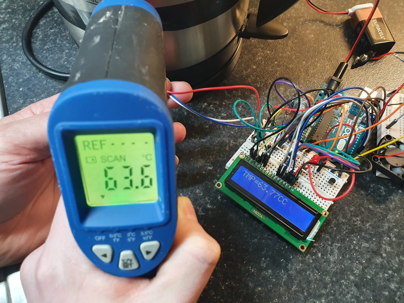
The project is a power amplifier and a modern take on a classic. It brings together digital elements of a temperature sensor and microcontroller, and the analogue elements of an amplifier with the aim of delivering pristine sound quality.
Thesis Title: Power Amplifier
A power amp or an audio power amp is one of the main parts of an amplification system. It is
placed between the preamp and the speakers. A power amplifier is a piece of equipment that
that amplifies low-power electronic audio signals such as electric guitars, microphones etc.
that are inputs to the preamp. The audio signals are boosted to a level of power which is
measured in watts that is high enough to drive headphones and loudspeakers.
The first power amplifier was built in 1912 by Lee De Forest (Audio power amplifier 2020).
He used an electrical component called the triode vacuum tube or valve that he too invented.
This device had three terminals with a control grid that could modulate the flow of electrons.
This design was used to make the first AM radio.
Today these valve amps are not as widespread and have been replaced with cheaper more
readily available amps made with electronic components. However, many musicians and
audio engineers prefer tube-based amplifiers as they tend to have a warmer sound.
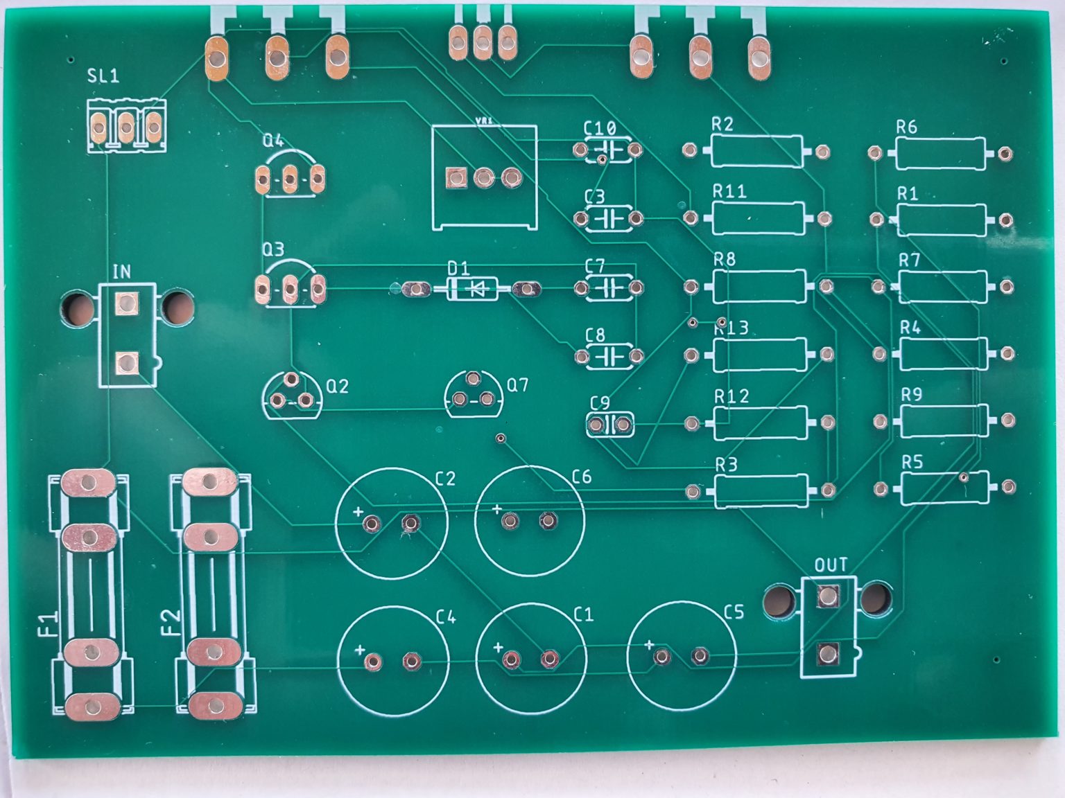
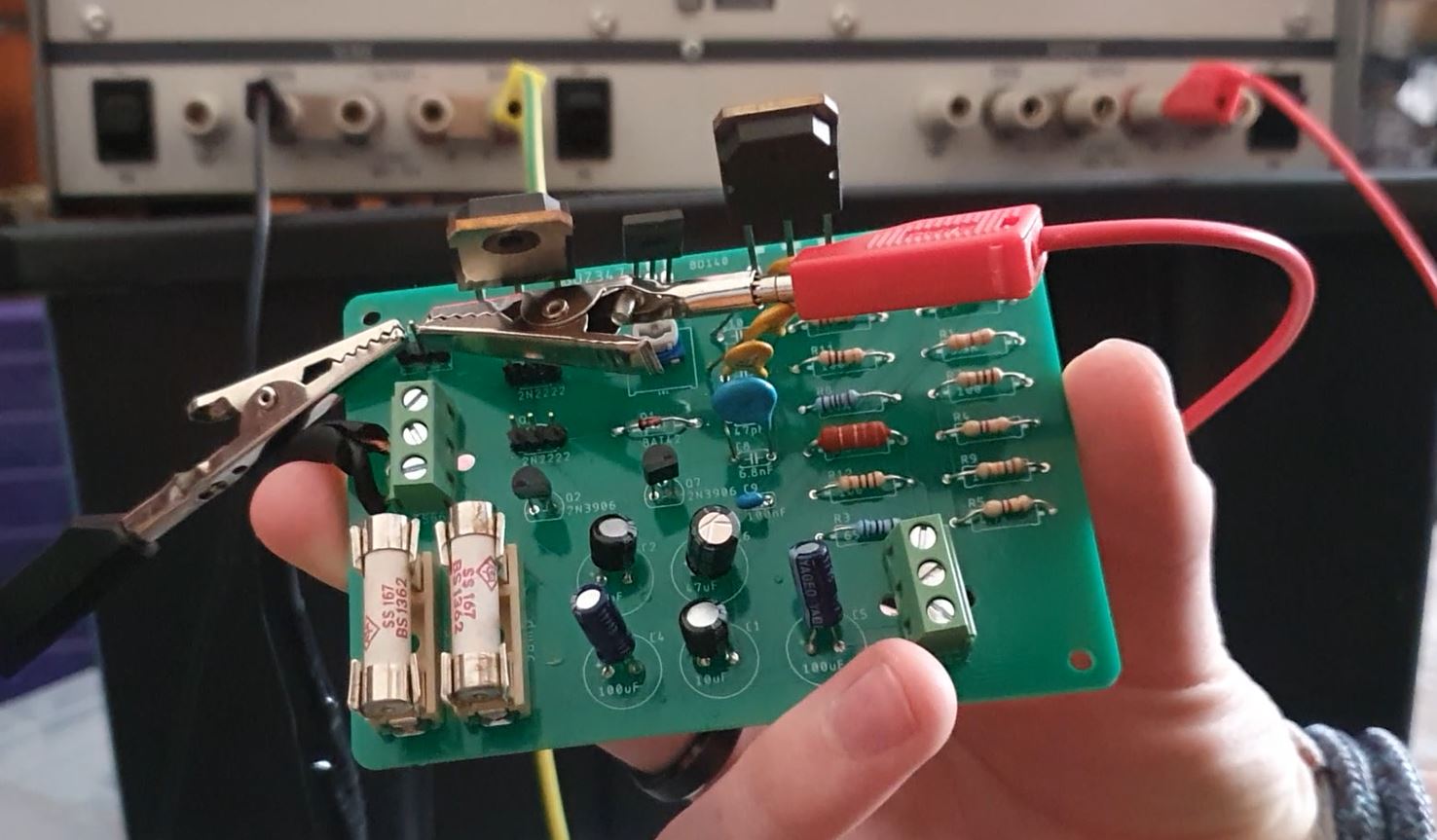
The aim of this project was to build a power amplifier by hand with the use of components,
soldering and software to simulate the circuits, using a collection of skills I have acquired over
the last four years at IADT.